
www.studioconnections.net.au
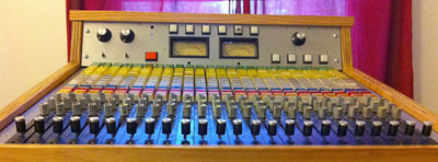
The API Summing Mixer was built from the monitor section of an API console combined with a Control Room Monitor system and dual independant stereo headphone systems.
The Summing Mixer was designed for use with digital work stations, to facilitate combination "in the box" and external analogue mixing. For example, you could combine returns from an external reverb unit with the DAW mix without having to return them to the DAW. For an entirely "in the box" mixdown, the Summing Mixer would act as a monitor only. A set of 8 unity gain Sub Inputs allowed you to send signals from the DAW directly to the submixer buses without going via input channels. In this way, auxiliary send buses set up in the DAW could be combined with the input channel sends in the API Summing Mixer.
For small to medium setups, a DAW combined with external mic preamps and this Summing Mixer could form the basis of a complete studio. This allowed for a wide variety of possible configurations with minimal need for customised wiring and additional monitoring devices.
All audio connections (except for the amplifier sends which were on XLRs) were on DB25 connectors so that standard "off the shelf" leads could be used to connect to DAWs, patch bays and so on.
The Summing Mixer was essentially a 24 into 10 router. All sends were pre-fade. All output gains were fixed (i.e. no master gain controls). There were no pan controls, but each channel could be assigned to one or more outputs to achieve L, C or R.
| Enlarge |
The signal path from any input to any output passed through only two active audio stages. The first was the balanced line input stage in each input channel. The second was the summing and line output stage, consisting of the classic API 2520 op-amp and transformer combination, as used in API consoles, mic preamps and EQ modules.
All signal routing was done with mechanical switches and relays. When a channel was muted or deselected from a mix bus, it was completely isolated from the mix bus. With all channels muted, the only active input to a mixing bus was the Sub Input.
In the case of the Sub Inputs, the custom balanced input stage design was similar to the ones in the input channels. These were unity gain from input to output and had the same input headroom and phase as the input channels.
All line inputs and outputs were +4dBm nominal with approximately 24dB of headroom (+28dBm maximum level), more than enough to accommodate the maximum output level of any DAW. All line outputs were transformer balanced and could drive 600Ω loads.
The mix bus outputs went to two DB25 connectors. These two connectors were wired differently to utilise all 10 outputs. (See Mix Path Block Diagram.)
The first was intended to feed DAW inputs. Mix 3-4 was intended for the main stereo mix. In addition, Cue 1-4 and Mix 1-2 could be used to achieve up to 8 outputs back to the DAW. These additional 6 outputs could be used to route mic preamps (or even a submix of various inputs) to DAW inputs. Analogue reverb returns connected to input channels can be routed either directly to the main mix or separately back to the DAW, using the switching matrix. This kind of flexibility could be especially useful for DAW's with a limited number of inputs and setups with no patch bay.
The second was intended for use as analogue reverb sends. Although there are only two outputs called Echo Sends, Cue 1-4 and Mix 1-2 outputs could also be used to achieve up to 8 reverb sends.
This example demonstrates how you could configure a small setup with some mic preamps (or other sources), some external effects devices and 16 channels of I/O with no patch bay, using "off the shelf" cables.

| Enlarge |
With this configuration, up to 16 channels could be recorded simultaneously and the API Summing Mixer would be used to provide the headphone mixes. The last two input channels of the DAW would be used for recording the mix back to the DAW.
This example is based on 24 channels of I/O, with 8 of them going to the API Summing Mixer inputs. Once again, this is achieved using "off the shelf" cables.

| Enlarge | Patch Bay |
With this configuration, up to 24 channels could be recorded simultaneously. The patch bay would allow inserting other analogue devices such as compressors into the record or mixdown path. By using the sub inputs, all headphone sends could come from the DAW during recording.
During recording, you could also patch inputs to directly to the Summing Mixer inputs and produce sub-mixes to feed back to the DAW inputs.
In both of the examples above, you could also connect more input sources to the Summing Mixer Line 2 inputs and use it as a router to feed up to 8 DAW inputs during recording.