
www.studioconnections.net.au
This project is a compact self-contained entertainment unit. Its primary role is a high quality music player.
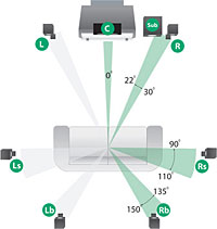
Speakers positioning is not negotiable for serious listening. The only thing that can be done is to make them as small as possible and supplement them with a common subwoofer. The positioning of the subwoofer is not critical. If you want video, you need a screen at the front of the entertainment area, at a convenient viewing height.
That leaves the remainder of the system. Ideally, you would combine all of these things into a single unit. In the past, this was probably a giant cabinet with your turntable, cassette deck, video player, amplifiers and so on. Now we can replace all of this with something much smaller. We don't need lots of separate players, except for the purpose of transferring stuff from old media. We could also include the subwoofer in the same unit.
The system must be designed to be simple and convenient to use, with minimal controls. The system should include:
I want the core system to last as long as possible. With things like the cabinet and the audio electronics this should not be a problem. I built an amplifier in 1968 which I still use.
One thing we can count on in the consumer market is that "standards" change! If you buy a dedicated entertainment system, it will almost certainly become obsolete within a few years. For example, the transition from analogue to digital TV broadcasts has taken place since the start of this project. The HD DVD standard never happened. Basing an entertainment system around a PC seems to be by far the best option at this time, allowing for the upgrading of individual components as long as possible into the future. Ideally, I would like to develop a microcontroller based system with its own operating system and player to escape the shackles of commercial hardware and software.
Although this project uses PIC microcontrollers, in general I do not believe in using specialised components, especially exotic audio chips, which have a nasty habit of becoming "obsolete" and unobtainable within a few years. I would rather use commonly available components where possible, even if this means an increase in circuit complexity. This concept worked well for MCI, whilst many newer so-called professional audio products became useless within a short space of time, due to the unavailability of specialised parts.
The human ear tends to be less sensitive to low and high frequencies at low listening levels. Traditional hi-fi amplifiers include a loudness switch to compensate for this effect. In low-end systems, this is just a fixed low frequency boost. In more expensive systems, the bass boost is higher at low volume settings, reducing to flat as the volume control is turned up.
However, very few systems have true loudness compensation. For a start, the overall listening levels need to be calibrated for the loudness compensation to work correctly. In the late 50's / early 60's, some manufacturers experimented with elaborate switched controls with hand-wired networks to perform this compensation. This was expensive and with the advent of stereo, most people conveniently tried to forget about the idea. Today, if anything, suitable rotary switches are even harder to obtain and the number of steps are limited.
The idea here is to construct a digitally controlled FET switching network. By carefully choosing the operating conditions of the surrounding audio electronics, it is possible to construct a high quality fully contoured loudness control with low distortion.
Most medium priced commercial units have a peak around 60Hz to accentuate the kick drum to make them appear to have a lot of bass, but fail to get to the lowest note of a bass guitar, let alone Low Frequency Effects (LFE). For that matter, most recording studio monitors don't get there either!
A well designed fully sealed enclosure is ideal for a subwoofer and will produce a smooth response, but it needs to be very large in most cases. Build a concrete enclosure the size of a refrigerator and I promise you will have bass! Ported designs allow much smaller boxes to be built to do the job, but they have limitations. Below the tuned frequency of the system, there is no back-loading for the speaker cone and the speaker can be easily overloaded or modulate the higher frequencies - the last thing you would want for a speaker that could be exposed to very low frequencies.
For studio monitor or domestic listening situations, one solution is to put the subwoofer into an undersized sealed box, which will have a predictable low frequency roll-off of 12dB/octave at a frequency which can be calculated, then use an electronic equaliser to compensate for this. The resonance of a large speaker in an undersized box will be relatively high, producing a peak at some higher frequency. However, this can also be compensated for with the electronic equaliser.
The down side of this is that you require an enormous amount of power for this to work. For example, if you require 20dB of boost at 20Hz to make the system flat, that means 100 times the amount of power needed to produce the same level at (say) 1KHz. The exact relationship between the power requirements for the main speaker system and the subwoofer depends on the relative sensitivity of the two systems. In practice, the energy levels at very low frequencies in most recordings are relatively low, reducing the demands on the subwoofer. As a rough guide, if you wanted to run your main speakers at around 30W, the subwoofer amplifier might need to be capable of handling 300W!