
www.studioconnections.net.au
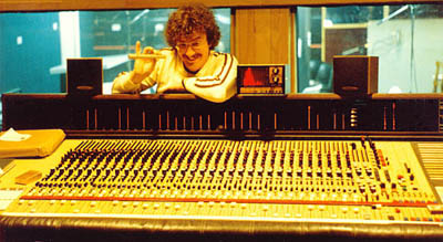
With the room lights dimmed this console looked amazing, with its EL back-lit meter panel, plasma meters and hundreds of LEDs. Its colours complemented the timber rich control room designs of the day.
The I/O modules had linear faders for the main (VCA) fader, small fader and two of the Auxiliary sends. This huge console could be back-breaking in a long session as you reached for the EQ and Channel Assign sections.
The JH-500 came in 28, 42 and 56 I/O channel frame sizes, the latter with the master modules in the centre. There were a number of options including the number of I/O modules, automation, plasma light meters or VU meters, a third octave spectrum analyser and an extra Auxiliary Returns module.
EQ's were four band non-parametric types. Because they used switches rather than potentiometers, they were very accurate. The mid range bands were fixed Q bandpass filters. The HF band could be switched as peak or shelving. There was also a variable frequency high pass filter.
The JH-500 had 32 bus outputs and 6 sends. Like the JH-400 series, it had a quad mix bus which was mixed down to a stereo bus which in turn was mixed down to a mono bus.
Unlike the JH-400 series and many other later consoles such as Harrison, Auditonics, SSL and Amek which had master status buttons for Record mode, Mix mode and so on, the JH-500 and JH-600 consoles had a much more straightforward yet versatile system - two master switches only:
The channel section of a JH-500 I/O module was the record path (Mic -> Channel Line Out), while the monitor section was always the mixdown path (Channel Line In -> Mix). Each I/O module had a VCA Reverse and Monitor Input Reverse button. The EQ could be switched to either the Channel section or Monitor section.
There were two independent stereo headphone send systems. Each of these had independent source selection and level controls. The Comms system fed these outputs directly, as opposed to feeding to the aux sends themselves. This allowed more flexibility in the way the aux sends were used.
This arrangement was quick to work with. For example, you could leave the console configured with the VCA fader in the mixdown path and the small fader in the channel path. In a busy studio where setup time was limited, you could throw up a mix and send it directly to the Cue system to get the session going. During the first few takes, you could be setting up more dedicated headphone mixes and at the flick of a switch, send them to the headphones. You could be setting up a final mix and even start automating it while you were still overdubbing! Try doing that on an old school Neve console! For that matter, try doing that on your DAW!
The JH-500 was the first to use plasma displays for metering. These meters were very accurate and switchable between peak, VU, the spectrum analyser or fader level. The ballistics were separately adjustable in Peak or VU mode and they could meet broadcast specifications for standard Peak and VU meters. The plasma meters were 100 segment types and the drive circuitry accented segments corresponding to key markings on standard meters. These accent points changed according to Peak or VU mode. In addition, the EL backlights changed to show either a Peak or VU standard scale. EL backlights also indicated master status and solo mode.
The JH-500 was the first console with automation. It was a tape based system, meaning that at least two tracks of the multitrack were tied up for automation data. When you performed an update, one data track would be read, the existing data combined with the updates and the result written to the other track. All automation controls were built into the console, along with controls to switch data tracks. The Plasma Light Meter option allowed you to view the VCA fader levels in real time. The process of reading data, processing it and writing it back took a 1.2 milliseconds. This delay was cumulative, so if you did enough passes with time-critical mutes, the delay could become noticable. Sometimes it would be necessary to re-write mutes towards the end of a mix.
It appears there were plans for an option to automate the quad pans as well, but I never saw such a thing.
Around 1982, DiskMix released a PC-based controller for ARMS automation. It interfaced with the automation data input and output and synchronised automation with a single time code track recorded on tape. This eliminated the cumulative time delay issue and made operation much easier (it was no longer necessary to juggle data tracks and press record when updating data). This crude DOS interface was surprisingly easy to use. This same system worked with other desks fitted with ARMS automation, such as the JH-400 and Sound Workshop consoles.
Each audio stage in the JH-500 ran off ±36V rails and consisted of a special high voltage IC buffered by two transistors. These were capable of driving a 600Ω load at up to +30dBm. Most of these stages operated at a nominal level of +4dBv. This resulted in a headroom of 26dB, double that of most other consoles! If there was a secret to the JH-500's superior sonic quality, I suspect it was due to this extra headroom.
The microphone preamp consisted of the same type of audio stage fed by a Jensen mic transformer. Like the JH-400, the output went to an insert point on the patch bay at a nominal level of -6dBm (10dB lower). This increased the effective headroom at this point to 32dB. This insert point was unbalanced and was designed for an old school compressor/limiter which was transformer balanced in and out and may have had an input impedance as low as 600Ω. (Many modern consoles using standard op-amps such as the TL070 series are not capable of driving a 600Ω load.) The first thing in the compressor/limiter was usually the gain reduction stage (either FET or opto) before hitting any active electronics in the device. In this way, the massive transients which tend to come from a microphone could be brought under control before returning to the console. The insert return went straight to the fader, meaning that it was almost impossible to overload the console, regardless of the return level.
There was a second insert point which could be switched pre or post EQ and it went with the EQ, which could be in either the Channel or Monitor section. This insertion point was also unbalanced, relying on the outboard gear of the day being balanced. The nominal insertion point level was +4dBm.
The Channel Line Inputs, Channel Line Outputs, Sends, Auxiliary Returns, Mix Outputs, Headphone Outputs, Studio Monitor and Control Room Outputs were all transformer balanced on the original JH-500. These were 1:1 transformers, mounted on the motherboards.

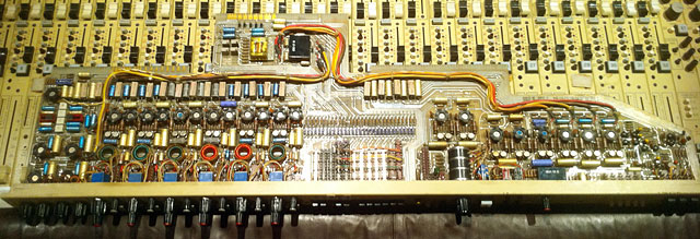
The MCI2002 IC was an Intersil HA-2645-5, chosen for its high slew rate and voltage capabilities. These days it is almost unobtainable. The S39568 and S39569 were 2N5681 and 2N5679 complementary transistors in T0-5 packages.
As time went by, production of the special IC ceased and supplies of the precious MCI2002 began to dwindle. In later versions of the JH-500, MCI used an alternative to the circuit shown above, based on an MCI2003M IC which was a 5534A in a T0-5 package.

This clever "swinging op-amp" design still ran off ±36V rails and the output of a 5534 is capable of driving 600Ω loads. Another bonus was that when used on a low impedance source such as a summing bus, the 5534A input stage is quieter. Not shown is the compensation capacitor Cn05, required for a 5534 IC and connected between pins 5 and 8. The value depends on the gain of the stage (22pF for unity gain).
MCI turned their attention to what was becoming the limiting factor in audio quality - the audio transformers. The JH-500B did away with the Channel Line Input transformers, replacing them with an electronically balanced input stage.
The JH-500C introduced the swinging op-amp design based on the MCI2003M, although some stages retained the MCI2002. The JH-500D went to MCI2003P (a 5534A in a DIL package) as well as MCI2004P (a 5532 in a DIL package).
The JH-500C/D also offered a choice of mic preamps, which were on a plug-in board: