www.studioconnections.net.au
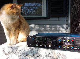
Audio Design (Recording) Ltd. is a UK based company, who have been around since the early 1970's. One of their more notable products was their Compex-Limiter, which was a combined compressor, peak limiter and expander/gate. The Compex-Limiter came in several forms including a separate vertically oriented module and a stereo 19 inch rack mounting version.
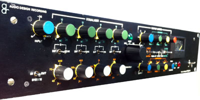
The Vocal Stresser consists of a single Compex-Limiter and an EQ section. The EQ can be switched pre or post the Compex-Limiter or into the side chain of the Compex-Limiter. In addition, when the EQ section is switched out, it is routed to a second set of XLR connectors, enabling the two sections to be used independently. At the time of its release (around the late 70's I think) it was a unique piece of gear and must have been attractive to studios on a budget, since it replaced up to four separate units in a single box. I know the engineers at Albert Studios used to fight for the use of the thing when they purchased one in 1979, to be shared between four studios. It was the closest thing you could get to a channel strip in a modern DAW!
ADR was one of the first companies to use a Field Effect Transistor (FET) as the variable gain stage for a commercial limiter, but on the other side of the planet, Bill Putnam developed this same technology for his famous 1176 limiter in 1966.
FETs are used as a variable resistor to attenuate the audio signal, followed by an amplification stage to restore the signal level. A DC voltage is used to control the resistance of the FET. The linearity of FETs is poor and in the most basic configuration, the distortion they produce is shocking! It became standard practice to feed some of the amplified audio signal out of phase back into the FET control voltage to cancel some of this distortion. Both the Compex Limiter and the URIE 1176 use this technique. Both devices have an adjustment which is critical to minimise the distortion. You need a distortion analyser to perform this adjustment. Even so, the distortion figures for FET based gain stages are relatively poor. The Compex-Limiter claims a "typical" figure of 0.04%, but in the lineup procedure it states a goal of less the 0.2%. This is not the entire story, since the distortion varies with gain reduction and the signal level. ADR also states a rather vague figure of 0.3% at +14dBm out. The 1176 states a conservative 0.5% at +24dBm out, but in practice the figures are usually better than that. Suffice to say that with all FET based variable gain stages, the distortion is audible. However, this was a major improvement on those variable gain valve compressors from the previous era. These days, that might just be the "sound" you're looking for, man!
The Compex-Limiter uses a single FET variable gain stage, shared between the compressor, limiter and expander/gate sections. At least this minimises the distortion, compared to using three separate FET based devices.
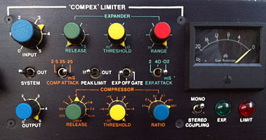
The peak limiting threshold is fixed and you need to know that the threshold is +14dBm (10dB above +4dBm) when the output control is set to maximum. Positioning the output control half way sets the peak limiting threshold to around +4dBm. The threshold control settings for the compressor and expander/gate sections are relative to the peak limiting threshold.
You have to juggle the input gain and compressor threshold to get the amount of compression you want.
Just to add to any confusion you may have about how this thing works, the stereo coupling switch does nothing! There is a vague reference to an option in the literature.
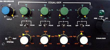
Each EQ band has an amazing ±20dB control range. What is not obvious from the front panel is that the bands have different Q's. The two inner bands have a Q of 1.5 (wide) whilst the two outer bands have a Q of 3 (narrow). Most units have different coloured knobs to signify this difference. There is enough overlap in the frequency ranges to allow for some flexibility, but a high pass filter would have been nice.
The Vocal Stresser has unbalanced line inputs and outputs, with balancing transformers optional. On unbalanced units, pin 3 is hot and rewiring the XLR connectors for the now standard pin 2 hot should be considered mandatory! The unbalanced outputs are only capable of delivering a maximum output of +18dBm. This is not really satisfactory for operating the unit at +4dBm line levels, although probably not too much of a problem when using the EQ in Pre or Side Chain mode. The optional transformers can be configured to boost the output levels to a +22dBm maximum, still leaving only 18dB headroom at +4dBm operating levels.
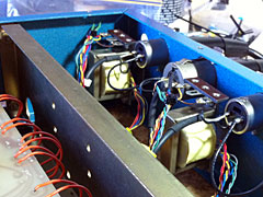
The unit I had to work on was fitted with output transformers only and these looked different to photographs of other units I had seen. I am not sure whether these were factory fitted. When I went to align the unit, I found there was a 1.75dB and 2dB loss in gain on the outputs and this was due to the transformers. I promptly disconnected them! Without them, both sections had almost exactly unity gain when by-passed.
Another annoying issue is that the back panel is not labelled properly. You are somehow expected to know that Channel 1 is the EQ when switched out and Channel 2 is the main I/O!
This is classic British engineering - over complicated, labour intensive construction, with glaring oversights! The serial number is on a hand-written sticker on the back of the front panel, making it impossible to read if it's installed in a rack. A metal strap, held in place by only one over-length screw, appears to have been added to prevent the front panel from flexing. The two main modules are built on separate sub-chassis, but it would be a mistake to think they were easily removable!
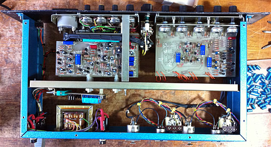


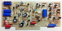
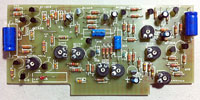
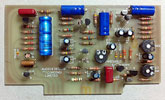
The Complex-Limiter has a small motherboard with three plug-in boards. You would think they would be in some kind of order but we start with Board B on top! There is no indication of where these are supposed to go and it would be easy to mix them up or even put them in up-side-down. To get these boards in and out, it is necessary to loosen screws on the front panel. During alignment, it is necessary to remove the bottom board to get at the preset adjustments on the middle board.
Despite the use of a motherboard, the wiring around the board is cluttered and complicated. Someone put in a lot of work to wire this thing up, all done with old-school lacing!
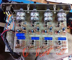
By contrast, the two EQ boards are hard-wired together and to the outside world. The only way to work on these boards is total disassembly, including removing the knobs. It is a nightmare to work on and there is always the risk of the wires snapping off whilst wrestling with the boards.
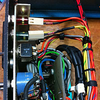
The Power Supply Board is on a gold-plated connector - the one place where this is actually undesirable, although there was no sign of any trouble in this unit. The board sits at awkward angle, and the heatsinks are tiny. At first glance, it looks like a ±15V supply, but it's actually two +24V supplies, one for each module. Fortunately, unlike many US products from this era, the transformer is designed to run on 50Hz, is quiet and runs stone cold. There is no voltage selector, but taps allow it to be wired for 230V or 115V.
By the end of the 1970's, most manufacturers had moved on to IC's. Even through the early 1970's when designing audio stages with discrete components, manufacturers such as Quad-Eight and API tended to use a different circuit topology such as differential pairs on the front end and balanced power supplies. I can only assume that these ADR designs had their heritage in the late 60's, even though the Vocal Stresser was released much later.
These types of circuits tend to clip asymmetrically and often have DC stability issues when overloaded. Nevertheless, there is no reason why a well designed circuit cannot perform well.
On the control side, these types of discrete circuits are limited in gain and stability and the penalty is that during alignment, many of the adjustments are inter-active, meaning you have to keep going over the same adjustments until finally everything comes together. They say the biggest issue with the Compex-Limiter is misalignment.
There is an up side to these old school designs with single power supply rails in that all of the audio coupling capacitors between stages usually have voltage across them. This makes electrolytic capacitors very happy and maintains their operational life. Audio coupling capacitors between stages with balanced power supplies are only there to block any small DC offset that a modern audio stage may have and consequently have no DC voltage of any consequence across them. This shortens the life of an electrolytic capacitor. Even worse, the offset could be negative and damage the capacitor. On top of that, the more complex designs of the 1980's often resulted in the units running hotter, which shortens the life of electrolytic capacitors even further.
In the case of the Vocal Stresser, the unit runs cool and has high quality capacitors installed and they are biased correctly, which is why these type of designs have tended to last for so long. Nevertheless, any electrolytic capacitor pushing 40 years old will be pretty much expired - and that only applies to the good ones used under optimal conditions! In the unit I had to work on, several had already been replaced, suggesting the writing was on the wall.
There were no actual faults with the unit I had to work on, apart from one physically damaged transistor which must have happened when someone removed one of the boards.
The original 24V indicator lamps assemblies were long gone. I managed to find some suitable LED/bezel assemblies that vaguely looked like the originals. It was necessary to install a series resistor for each of the LEDs.
In the original unit, you had to unsolder the lamps to remove the front panel or the Compex-Limiter sub-chassis. I installed sockets for the LED indicators, which are mounted on the front panel. It was an elegant solution. At least this made one aspect of working on this thing easier!

Unfortunately, the meter glass was smashed in this unit. I took the bezel assembly to a glass supplier who proceeded to destroy it in front of me whilst trying to get the old glass out. The "picture glass" they had was 2mm thick - too thick for the meter anyway. So now I not only had no glass, but I had a broken bezel as well! Some good person on the internet suggested using the blank disk you get with CD's. I used a sharp knife to score and then snap it. A bit of light sanding of the edges and it fitted perfectly. I then had to glue the broken bits of the bezel together as best I could. Thanks, you moron glass man!
Then there was the physical cleaning of the front panel and knobs.
Another issue was that two of the captive nuts on the EQ sub-chassis had come loose and needed pressing back into place.
The major task was to re-cap the unit. There are nearly 60 electrolytic capacitors, making this a big job. Working on the EQ section was particularly difficult. When replacing axial electrolytic capacitors, I like to use axial replacements, which are not readily available from most suppliers and usually expensive. I like the Vishay/BCC (formerly Philips) 138 Series which are 105°C, long life types. The higher temperature rating translates to even longer life expectancy when operated at lower temperatures. Due to cost considerations, I ended up using conventional radial 105°C capacitors for the smaller types. Theoretically, the expected life of all these capacitors should be longer than the originals, which were already pretty good.
All switches and pots were cleaned with De-Oxit D5 spray and upon firing the unit up, some of them required further attention.
Next came the alignment. Apart from the curved ball thrown at me by the output transformers, in general it was straight forward but complicated. It was not until you touched things not mentioned in the instructions that you would find yourself going in circles. For example, I adjusted the compressor rectifier balance after replacing the transistor which meant starting the alignment from scratch again. At the end of the day, everything came together well within specification.
Now, it will be interesting to see what the owner thinks of this device. It's going to be up against some stiff competition!