www.studioconnections.net.au
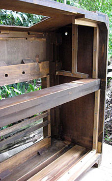
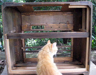
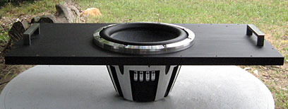
The cabinet had two wooden bars across the speaker opening. The cone surround of the subwoofer I wanted to use protrudes beyond the front of the speaker, meaning it would have to be rear-mounted. Allowing for the thickness of the baffle, rear panel and clearance for the breather hole on the back of the speaker, this massive speaker simply wouldn't fit inside the box!
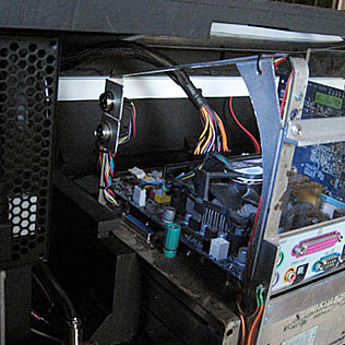
The only option was to mount the speaker on the back of the rear panel, which is laser cut from 25mm MDF, facing backwards.
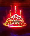
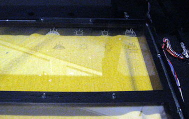
Front Panel DesignI replaced the original front baffle and grille cloth with a thick clear acrylic panel, so you can see inside. The speaker is designed to look good from the rear. The Front Panel is made up of three layers, totalling 21mm thick. These panels are also screwed to the ornamental wooden bars running across the front of the opening to help keep the assembly solid. The front 3mm layer was laser-etched on the back with the HMV logo and edge-lit by a set of red, green and blue LEDS mounted on the HMV Logo Board which slides into slots inside the cabinet to allow for alignment. The edges of this layer were covered with reflective foil to help light dispersement within the layer. 
HMV Logo
The second 3mm layer was laser-etched with four symbols to be lit by the Standby, Power, Message and HDD LEDs from above. These LEDS are less powerful since two of them are driven directly by the motherboard electronics. The edges of this layer are covered with black tape to eliminate any other light source and reduce internal reflections. 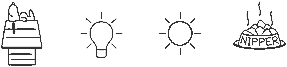
Standby, Power, Message and HDD indicators
The third layer is 15mm thick to strengthen the front panel. |
FRONT PANEL DRAWINGS
When first designing these I didn't know about laser-etching and was planning to get them engraved. Engraving machines behave like a plotter and require a vector drawing. Producing these images was a nightmare! First I had to find bitmap images. They had to be reduced to black and white line drawings in PhotoShop. In the case of the His Master's Voice painting, this required manually tracing over the image on a new layer. I then exported these as JPG files. These were put into CorelTRACE to produce a vector drawing in DXF format. Initially, ancient CAD program had trouble importing these files and I had to go back to PhotoShop to simplify them even further, then repeat the whole process. Even then, some of them were beyond my CAD program and I ended up with an incomplete image. The next problem was that CorelTRACE produced polyline drawings, unsuitable for engraving machines. I had to manually recreate the drawings yet again on a new layer in my CAD program, using lines, circles and curves! This process took forever. |
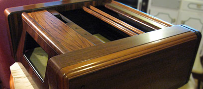
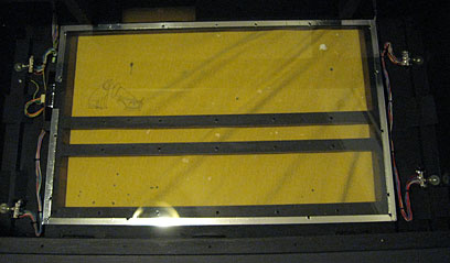
The speaker enclosure area needs to be sealed. This is not as easy as it sounds because the top of the original speaker baffle sticks up past the bottom of the Main Chassis, making sealing the top extremely difficult. The new clear acrylic Front Panels which will go in place of the original baffle will have to be fitted first, then the top Brace Panel fitted and sealed around it. And the whole thing is going to have to be removeable, so I can remove the acrylic panels while the cabinet is being refurbished.
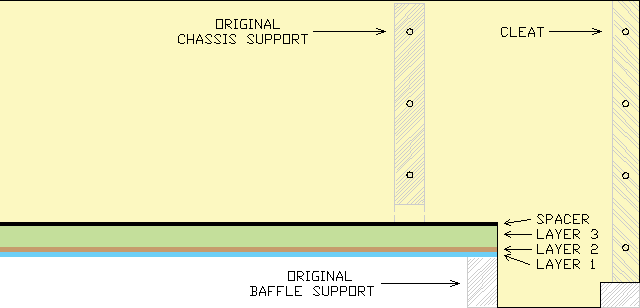
Because the Front Panel is now clear, the top 20mm of the opening needs to be blacked out to prevent the Brace Panel from being exposed, since it is below the top of the front opening. A special laser-cut 2mm black acrylic Spacer Panel was designed to fit behind the Front Panels. Because this black panel is so far back and the internals of the enclosure will be painted black, it will hardly be noticable.
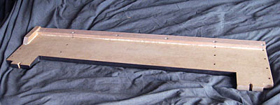
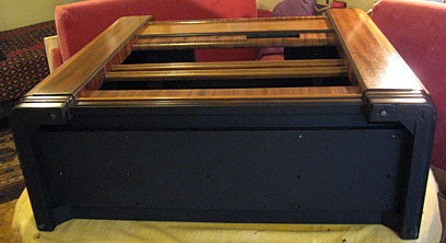
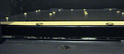
The original baffle was recessed and the Brace Panel which forms the top of the speaker enclosure area has to fit tightly around the Front Panel, the Spacer panel and the existing internal woodwork. This is laser-cut from 16mm MDF.
Cleats attached to the side of the cabinet strengthen the structure and the original chassis supports are bolted to the top of the Brace Panel.
After months of producing drawings, the moment of truth has arrived! Theoretically, I email them off to the supplier and get the completed items delivered in a few days. If I have made a mistake I'm screwed...
Time passes...
My worst fears are realised when I receive the items and to my horror discover that despite all my hard work and double-checking measurements with printouts of my drawings, I've somehow managed to screw up the three front panels which all came from the one master drawing! Naturally, these were the most expensive and critical part of the exercise - a problem with one of the other items would have been no big deal. I'll leave it to your imagination to guess the exact number of expletives that were issued!
Fortunately, I found a way around the problem. Now that I have finally worked out all the details and made all the fiddly bits, it's time to strip everything out of the cabinet to work on it...
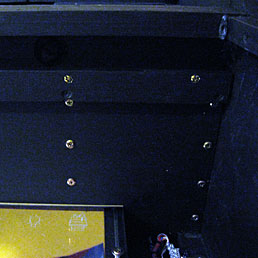
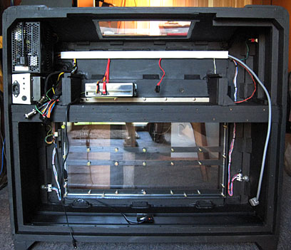
Cleats were fitted to the cabinet to support the Speaker Baffle, the speaker enclosure top Brace Panel, the Power Amplifier and some rear cover panels.
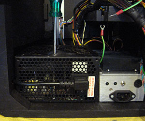
To allow clearance for the Computer Power Supply and The Dog Box, part of one of the cleats was attached to the Brace Panel. (Yes, space is that tight!) Another cleat secures the rear edge of the Brace Panel to the original cabinet horizontal bar.
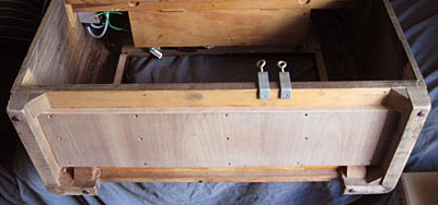
I removed a plywood panel which was attached to the bottom of the chassis support bars to cover the bottom of the chassis. Instead, the Brace Panel will be screwed directly to the chassis supports.
I also removed a bar running across the bottom of the speaker enclosure at the back and fitted this across the middle of the bottom of the cabinet. An additional piece of plywood covers the gaps between the slats and gives enormous strength to the base.
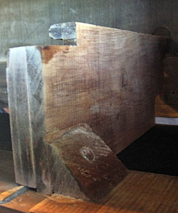
Apart from the cabinet side panels, the chassis supports are the only things connecting the rear bar to the front of the cabinet and these were loose. I temporarilly removed the chassis supports.
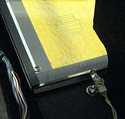
The new Speaker Baffle is 25mm thick, but the original horizontal bar is only 23mm from the rear of the cabinet. A 2mm rebate was cut into the top 50mm of the Speaker Baffle to account for this difference.
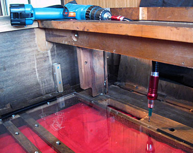
Before reinstalling the chassis support bars, the Brace Panel and Speaker Baffle were bolted in place to securely position the horizontal bar. Part of this process was to drill pilot holes for the screws to secure these panels.
After installing the chassis support bars, I poured polyurathane wood glue into the joints to permanantly secure the horizontal bar. Whilst at it, I poured glue into every orifice inside the cabinet I could find to generally strengthen the joints.
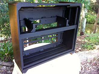
Well, that's about all I can do for the cabinet preparation. Now it is out of here to get polished.
In the meantime, there is work to do on the cabinet sub-assemblies.

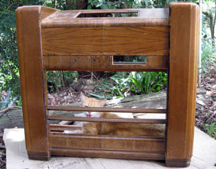
It's back! And what an amazing job! It looks awesome!
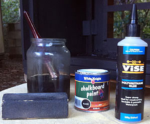
Now, a final touch-up with the black paint and I will finally be able to put this thing together...
1. The
bezel simply pushes snuggly into a 16mm diameter hole. This
actuates a modern momentary switch mounted inside which is the ON-OFF
switch.
|
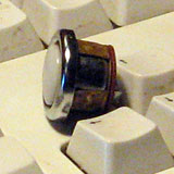
Original 1941 Switch Bezel.
|
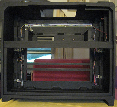
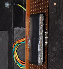
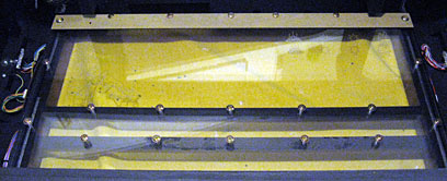
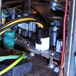

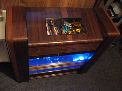
LED circuits #6 - #9 are bounced off reflective tape on the side of the speaker enclosure area onto the rear of the speaker. LED circuit #10 - yellow - has some extention cables fitted to move the bottom two to the middle front, aimed directly at the front of the speaker, while the top two are aimed directly at the top of the speaker. This creates distinctly different lighting angles to the other circuits and when alternating between LED circuit #10 and any of LED circuits #6 - #9 a sense of movement can be created.