
www.studioconnections.net.au
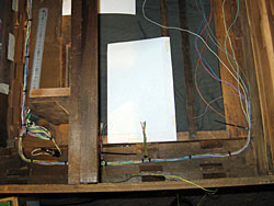
The interface electronics resides in a narrow area down the right hand side of the Main Chassis. This must clear the right hand side of the Blu-ray/DVD drive. Additional brackets support the circuit boards.
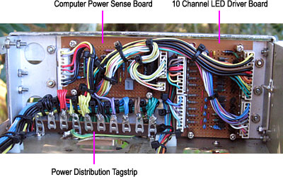
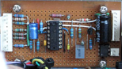
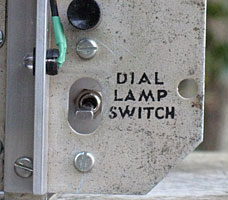
This small board has several purposes in life. It controls the Power and LED indicators. It also controls the Power Relay, located in The Dog Box. An opto isolator ouptut is used to control amplifier muting.
| View Schematic |
The Power LED is fed from the Computer +5V rail via R6, which was chosen to match the brightness of the Message and HDD LEDs.
The Computer +5VSB rail is permanently active and is used to power an LM339 quad comparator IC with open collector outputs (U1).
U1B detects when the system is shut down by monitoring the Computer +12V rail. The output of U1B controls the Standby LED. The LED brightness is determined by R5.
When the system is first powered up, a timer consisting of R11, C3 and U1C delays the activation of the Power Relay for approximately 1 second. U1D monitors the Computer +5V rail. U1A monitors the Computer Power Power Good signal. If the system is powered down or the mains drops out, U1D and/or U1A reset the timer by rapidly discharging C3 and the Power Relay is turned off instantly. Once this happens, the timing cycle must complete before the Power Relay can be turned back on again.
The Power Relay drive circuitry is powered by the Computer +12V rail via R16. When the Power Relay is inactive, C4 charges to +12V. When the relay is first activated, full power is applied to the relay coil, due to the charge stored in C4. The current through the coil at this instant is approximately 35mA. Relays only require about one third of the current to remain closed after they are activated. Due to R16, the current drops to approximately 20mA to conserve power.
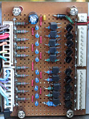
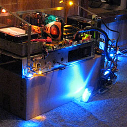
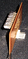
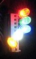
This board drives the chassis and cabinet lighting.
Each channel is a switchable analogue current source, capable of delivering up to 100mA. A channel is switched on by grounding its input and requires either a switch or an open collector driver to control it.
The LED Controller Board generates 10 PWM signals to control the brightness of each channel. In addition, the rear lights and chassis illumination lights (channels 1 and 2) can be turned on manually by a switch on the rear of the chassis.
| View Schematic |
The maximum current (IMAX) for each channel is chosen to suit the type of LEDS used in that channel and is set by resistor Rn03 as follows:Rn03 = 0.6 / IMAXSince the LED drivers are powered from the +12V computer rail, the maximum number of LEDS that can be wired in series on the same channel depends on the type of LED. Red, orange and yellow LEDs usually have a forward voltage drop (VF) of around 2.2 - 2.5V and there can be up to 4 on the same channel. On the other hand, green, blue, aqua and white LED's have a VF of around 3.3 - 3.5V, limiting the maximum to number to 3.Assuming either 4x LEDs @ 2.2V or 3x LEDs @3.5V, this represents a regulator efficiency of around 73% to 88%. For higher current channels, the minimum number of LEDs should also be considered. For example, for a 70mA channel there should be a minimum of 3 LEDS to limit the heat dissipated in the driver transistor (Qn02).The RGB HMV Logo has 3 LEDs for each colour. A set of trimpots accessible through holes in the rear of the Main Chassis are used to set the correct white balance.
The chassis power wiring was covered in Power Distribution. Other Chassis wiring includes LEDs, connectors, switches, the Computer Motherboard, Computer Sense Board and 10 Channel LED Driver board.
| View Schematic |
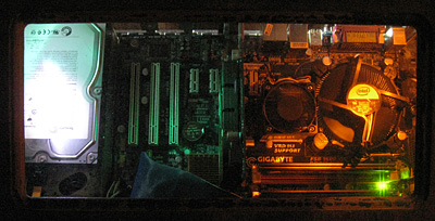
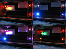
Channels 1 and 2 of the 10 Channel LED Driver Board are used for the rear lights and chassis lighting.
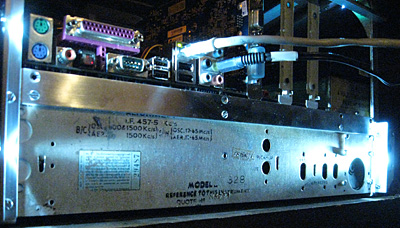
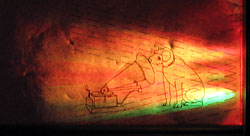
The main purpose for the rear lights is to assist in connecting things to the computer and the rear chassis connectors. In my long-term plan, the chassis illumination will only be seen from the back of the unit. In the short term, until I find a suitable touch screen it will also be seen from the front through the cabinet cutout for the old tuning dial.
Both of these sets of lights also throw light onto the wall behind the unit and can be part of the overall lighting effect.
In addition, the Power LED (driven by the Computer Power Sense Board), the Message and HDD LEDs (driven directly by the computer motherboard) are mounted on the chassis but shine into the speaker enclosure area.
This includes wiring to:
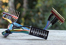
All of the low voltage cabinet wiring is in one loom, connecting via a single DB25 connector (P3) to the Main Chassis. I pre-made this loom, cut and shaped to fit the cabinet. When the speaker enclosure area is sealed, it will not be removeable!
| View Schematic |
The Standby LED (driven by the Computer Power Sense Board) is mounted directly on the cabinet in the chassis area but shines into the speaker enclosure area.
Ch 3-5 of the 10 Channel LED Driver Board are wired to a socket which connects to the HMV Logo Board inside the speaker enclosure area.
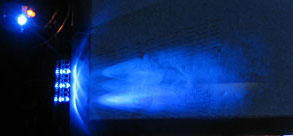
Ch 6-10 of the 10 Channel LED Driver Board are wired to 10-way 0.1" (2.54mm) receptacles, mounted in the 4 front corners of the speaker enclosure area and hidden from view. These sockets are wired in series and up to 5 LEDs can be inserted into each of these sockets. There can be up to 4 LEDs per channel only if they are red, orange or yellow. For other colours where there can only be 3 LEDs per channel, the 4th position must be by-passed with a link. Using this socket system allows LEDs to be easily changed and allows versatility in the final lighting setup. If necessary, an individual LED could be relocated by plugging in a 2-pin header and extension cable.
All LED's except the ones mounted on the HMV Logo Board are on sockets. There are 36 high efficiency, high power (and high priced!) 5mm LEDs used in this project.
This is the current lineup:
| Cct | Description | IMAX | Rn03 | LEDs |
|---|---|---|---|---|
| 1 | Rear Lights | 27mA | 22R | 3x ZD0280
|
| 2 | Chassis Illumination | 27mA | 22R |
1x ZD0284
1x ZD0285
1x ZD0178
|
| 3 | HMV Logo - R | 5mA-50mA | 112R-12R | 3x ZD0283 |
| 4 | HMV Logo - G | 5mA-50mA | 112R-12R | 3x ZD0282 |
| 5 | HMV Logo - B | 5mA-50mA | 112R-12R |
3x ZD0281
|
| 6 | Speaker Rear - R | 67mA | 09R | 4x ZD0283 |
| 7 | Speaker Rear - G | 50mA | 12R | 3x ZD0282 |
| 8 | Speaker Rear - B | 27mA | 22R |
3x ZD0291
|
| 9 | Speaker Rear - W+B | 50mA | 12R |
2x ZD0280
1x ZD0281
|
| 10 | Speaker Front | 67mA | 9R | 4x ZD0284 |
| - | Standby Indicator | 1.5mA | - | 1x ZD0285 |
| - | Power Indicator | 10mA | - | 1x ZD0282 |
| - | Message Indicator | - | - | 1x ZD0284 |
| - | HDD Indicator | - | - | 1x ZD0283 |
The part numbers shown above are all Jaycar Electronics catalogue numbers.
I had trouble with LED failures over the first 18 months. Some developed excessively high forward voltage, some just died unexpectedly, some lost brightness whilst others flickered at specific light levels. I even had one which was somehow wired internally back-to-front - it worked fine when installed backwards!
I had been careful to observe their maximum ratings and no LED spends much time at its 100% level. I suspect some were from bad batches. I began to notice a pattern where they tended to fail when first switched on at low temeratures. The thermal characteristics of the current source circuits on the 10 Channel LED Driver Board are such that the current increases at low temperatures. I ended up modifying the startup routine of the LED Controller Board so that all LED circuits came on slowly and prevented any LED from operating at full brightness for the first 60 seconds. Since then, I have had no problems.
More recently, this range of LEDs has been discontinued and I have been successfully trialing some Cree types (ZD0291), although these have less exotic ratings.