
www.studioconnections.net.au
The LED Controller Board is an intelligent controller for the cabinet lighting, capable of switching or fading between internally stored scenes and responding to music. Normally it operates independently, relying on the music as its only stimulus. It includes a serial port and ultimately the plan is to write software for the main computer to select or edit scenes.
The LED Controller Board is based around a Microchip PIC16F88A microcontroller IC. This little guy has flash memory for storing the program, which means that the program can be updated. Furthermore, it features "In-Circuit Serial Programming" (ICSP), which means I can create and update the program at my leisure on my computer and then download it to the board without removing the chip from the circuit.
This PIC16F88A is an 18-pin DIL chip which includes a multi-input D/A converter and a serial interface. Most of its pins can be programmed as either analogue inputs, digital inputs or digital outputs. With 2 pins tied up for power, 1 pin for the Reset/Test switch, 3 pins configured for the SPI serial port and 2 pins configured for analogue inputs, that leaves 10 pins to configure as digital outputs for 10 lighting channels.
The LED Controller Board generates 10 sets of Pulse-Width Modulated (PWM) signals. The PWM signals are digital and switch the current sources in the 10 Channel LED Driver Board either "on" or "off". The ratio of the time it spends "on" to the time it spends "off" is called the duty cycle and this determines the effective brightness of the LEDs. A 100% duty cycle means the signal is permanently "on", and the LEDs operate at their maximum brightness. The PWM signal must switch at a sufficiently high rate so that the human eye cannot detect any flicker.
One problem with using sound to control lights is that audio levels can vary enormously. For a start, there is the nominal operating level of the sound card. I ran a few tests on my RealTek HD audio chip built into the GigaByte GA-EP31-DS3L motherboard before using it. The low end frequency rolloff was unmeasurable at 10Hz into a load of 10KΩ. The measured output level was +4.5dBm when playing a 1KHz tone at 100% FS with all mixer controls set to 100%. The measured distortion at this level was 0.004% I am guessing this means that the sound card output stage runs off the +5V rail and there are no output coupling capacitors.
Unfortunately, there is a wide variation in recording techniques, mastering levels and the amount of compression used with music recordings. When playing an arbitrary set of music files, the average recording level varies enormously, particularly when mixing recordings done in different eras. Sound tracks on DVD's and Blu-ray also vary in level, as do television levels. Often, this difference can be objectionable. This problem becomes even more serious when trying to use sound to control lighting.
Fortunately, Winamp and many other music players these days include a Replay Gain Analyzer. In Winamp, there is a setting for the gain adjustment for files without replay gain information, which by default is -6dB. When playing my reference 1KHz tone at 100% FS which does not have replay gain information, the output level is -6dB with respect to maximum output. When playing typical music files with the Replay Gain Analyzer enabled, the average output level was roughly between -20dB and -10dB. This is still not perfect (some recordings are so flattened that there is not much you can do about it), but I find this is a major improvement.
I experimented with an Automatic Gain Control with a very long release time but found this did not work well when a soft song followed a loud song - it took too long for the thing to get going again. Instead, I elected to use a fixed gain approach with a crude form of limiting which sets a level range window to work in. The gain is optimised around my system running Winamp with the Replay Gain Analyzer enabled.
The two filters which separate the low and high frequencies have an intentional gap between them to separate the bass and kick from the rest of the program. The filters feed two rectifiers which produce DC voltages proportional to the loudness of the two audio channels. These DC voltages are fed to the PIC analogue inputs and the limit detectors which control the rectifier gain.
In this design, the Low and High channels are customised to behave quite differently and you can clearly see the difference when playing music.
Bass content is one thing that varies greatly in different music mixes. The Low channel responds to music peaks. It is more sensitive than the High channel and it relies on the limiting to pull the bass into line. It is specifically designed to respond to the kick drum and on recordings with heavy kick content, it pumps the DC signal between 0 and 100%. It also picks up on things like body slaps on an acoustic guitar. On recordings where sustained bass is more dominant, it responds to this instead but tends to operate in a more linear fashion.
The High channel responds to the average music level. The High channel also has limiting, but the effect only kicks in at high levels. This channel tends to act more like a standard VU meter.
Originally, I intended to do a logarithmic conversion of the A/D result in software to get a brightness level proportional to the perceived loudness level. This is commonly done in audio console meters to obtain a scale in decibels. I used a lookup table to perform the conversion. When I got it going, I found that this reduced the brightness variation with most music and this only highlighted the lack of dynamics in many recordings. The results were unexciting. Since I already had the lookup table system in place, I ended up fiddling the table values to taste to get the best visual result.
I wanted my lighting to respond the mood of the music and for the reasons stated above, just looking at the sound levels is almost useless. I created a set of Event Detectors to allow decisions to be made about the type of music.
In software there is a set of constants which can be adjusted to fine-tune timing periods and level thresholds for the event detectors.
Lighting Scenes are a set of parameters, stored in a dedicated Flash EEPROM data memory area of the PIC16F88A which consists of 256 bytes. Each scene uses 13 bytes. There can be up to 18 scenes stored in this area, the remaining space being used for key program settings. Within each lighting scene, three bytes are used for Global Scene Settings, whilst the remaining 10 are specific to each LED channel.
Each Channel Preset is a single byte consisting of a 3-bit code to specify the A/D mode for the channel and a 5-bit number to specify the Preset Level for the channel brightness (0 - 31).
The A/D modes are as follows:
By using different A/D Modes and Preset Levels on each channel, just one static scene can produce a variety of effects.
Depending on the results of the Event Detectors, the LED Controller board switches between Normal Mode and Hyper Mode. Hyper Mode allows stuff to happen which would be inappropriate for more mellow music!
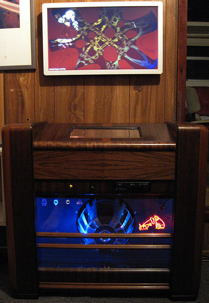
The presets for LED channels #7 and #8 (which are the green and blue channels for the speaker illumination) are swapped, triggered by Beat Detector 0. This produces a rocking action in time with the music on recordings with regular beats.
The presets for HMV Logo LED channels #3 (R), #4 (G) and #5 (B) are rotated, triggered by both Beat Detector 0 and Beat Detector 1. For example, if R = 100%, G = 0% and B = 0%, this is what would happen:

Repeating this process would result in blue, whilst repeating again would return the colour to red. Therefore, a maximum of 3 different colours can be produced by this process.
The Preset Levels for the RGB channels are also inverted when a Beat Detector 0 or Beat Detector 1 event occurs. For example, if the Preset Level for a channel is 25%, it becomes 75%. This effectively reverses the colours. For example, if the colour was red, the following would happen:

Repeating this process would return the colour to red. Therefore, a maximum of 2 different colours can be produced by this process.
If the A/D mode is a scaled mode, the A/D mode itself is also inverted. For example, if the mode was "Add Scaled High Sound Channel to Preset Level", the Preset Level would usually be relatively low. When inverted, the Preset Level would now be high and the A/D mode would become "Subtract Scaled High Sound Channel from Preset Level".
If the RGB channels are inverted and rotated in one step, this produces a total of six different colours after doing this six times. Here are some examples:


EXtrEmE Mode is just an extension of Hyper Mode and the difference is only in the choice of scenes. For example, the HMV Logo in the default scene for Hyper-Mode switches between secondary colours at low levels, going white at high levels. This works well with dynamic music, but it tends to just stay white at constant high levels and you hardly notice the colour switching. Under these circumstances, Loud Detector 1 triggers a change to a set of scenes which are designed for this situation. For example, one EXtrEmE scene has the HMV logo going to primary colours at high levels instead of white, while another ignores sound levels completely and switches between fixed colours only. Yet another has no colours at all and works on just the beat detectors, producing a strobe-like effect.
In general, the scenes used for EXtrEmE mode tend to change more often and there are more of them. By contrast, I have only bothered with one scene for Hyper mode so far, since this works so well. In practice, the LED Controller only switches into EXtrEmE mode briefly, if ever, with most music. Consequently, it rarely gets past the first EXtrEmE scene, so subsequent EXtrEmE scenes can afford to be more radical!
In addition to duration timeouts, scene switching is triggered when the LED Controller changes modes.
The audio input stage is a fully symmetrical balanced line receiver consisting of IC100C and IC100D. This design has better Common Mode Rejection Ratio (CMRR) performance than a standard single stage balanced line receiver. It has a gain of up to 10dB and an intentional high frequency rolloff above 20KHz. This stage is used to sum the audio inputs and each input has an effective input impedance of 100K across the unbalanced sound card outputs. The analogue circuitry on the LED Controller Board is referenced to Digital Ground. The balanced input configuration is used to interface with the signal sources which are referenced to Analogue Ground.
A 72Hz Low Pass Filter (LPF) consisting of IC100A feeds the Low sound channel, while a 160Hz High Pass Filter (HPF) consisting of IC100B feeds the High sound channel. Both these filters have a rolloff of 12dB/octave.
The two audio channels are rectified to produce DC voltages proportional to audio levels by IC200. Instead of the usual full wave precision rectifier circuit, this design has two separate half wave rectifiers with the outputs connected together via diodes.
The Low channel rectifier charges C201 via D205. The voltage across C201 is proportional to the peak level of the audio signal, with R210 and R211 determining the decay characteristic. The High channel rectifier charges C203 via R223. The voltage across C203 is proportional to the average level of the audio signal.
These two DC voltages are sent to two A/D inputs of the PIC MCU via R6 and R7. These resistors limit the input current when the voltage exceeds +5V. The A/D is configured to operate over the range from 0V to +5V.
The two DC voltages are also buffered by Q201 and Q202 respectively, which feed the network consisting of ZD201 (ZD202), R212 (R224), D206 (D211) and C202 (C204). When the DC voltages exceed 5V, C202 (C204) begins to charge. Note that because the zener diodes are operating at currents well below their nominal current, their zener voltage tends to be lower and these 5.1V types work at more like 4V. The decay is governed by R201 (R213), R203 (R215), R205 (R217) and R207 (R219) and is relatively slow. The voltage across C202 (C204) is fed back to the inverting input of the rectifiers and this effectively raises the input threshold of the rectifiers. This, in conjunction with the rectifiers clipping, has a limiting effect on the DC voltages. When there is a charge across C202 (C204), the rectifiers work over a much smaller window, because the threshold effectively eliminates lower level signals. It ain't pretty, but seems to work well with music.
For normal music tracks, the High channel operates mostly in its linear region. The Low channel is much more sensitive because the rectifier has higher gain and it works with peak rather than average signal levels. Tracks with heavy bass really hammer the thing and the result is that C202 builds up a charge. It's under these conditions that this circuit really turns feral! In between heavy kick drum beats, the rectifier completely cuts off. This may happen at levels as little as 6dB below the maximum level. This effect, in conjunction with the fast attack time of the Low channel rectifier makes the circuit particularly responsive to kick drums. The time constants are chosen to make the thing really pump on tracks with heavy kick content.
The ten pins on the microcontroller used for the PWM outputs drive two ULN2003 open collector transistor array IC's via 10K resistors. The ULN2003's isolate the PIC outputs from the outside world. For some applications these could be used to drive LEDs with series resistors directly. However, in this project they are used to control the current sources on the 10 Channel LED Driver Board, which are fed from the +12V rail. This arrangement tolerates shorts in the external LED wiring without damage.
The ICSP Connector connects to the RA5/MCLR/VPP, RB6/PGC and RB7/PGD pins, which are isolated from the rest of the circuitry by 10K resistors. Note that this connector also includes a +15V output and this, in conjunction with the standard Vdd (+5V) output, powers an external programmer without the need for additional power supplies.
The SPI Port connector has a 10K resistor to ground across the Serial Data Input (SDI) line. This ensures that the port sees 0's when no host is connected.
The power connector is the standard format described earlier in Main Chassis Power Distribution.
| View Schematic 1 | View Schematic 2 |
This software was written in Assembly language, using the MPLAB Integrated Development Environment, available as a free download from Microchip.
This is based on the Microchip Application Note AN1074 - Software PWM Generation for LED Dimming and RGB Color Applications, expanded from 3 PWM outputs to 10.
The main program initialises variables, configures the role of the
pins and configures the internal modules in the PIC chip.
It sets the variable SegCount to 32 before starting
an internal timer called TMR0. This timer is
configured to generate an interrupt when the timing period has expired,
which causes the program to jump to the Interrupt Service Routine (ISR).
Most of the action takes place in the ISR and its associated subroutines.
When the ISR runs, it restarts TMR0, set to a timing
period of 322µS and decrements SegCount by 1,
meaning that the first time it runs, SegCount = 31.
The next time it runs, SegCount = 30 and so on until it
reaches 0, at which time it resets SegCount to 31.
Thus, the ISR runs every 322µS with SegCount counting
down from 31 to 1.
In this design, a complete PWM cycle is divided into 31 segments which makes it capable of creating 32 different brightness levels by having 0 - 31 segments on. A complete PWM cycle takes approximately 10mS (31 x 322µS), meaning a refresh rate of about 100Hz.
A set of 10 variables LEDCont0 - LEDCont9
control the brightness levels (0 - 31) for the 10 channels.
Each time the ISR is called, all 10 LED channels are processed.
A specific LED channel is turned on if
LEDContn >= SegCount.
A channel with a setting of 31 would activate the LED on the first
segment and it would remain on for all subsequent segments. A
channel with a setting of 16 would be off for the first 15 segments and
then on the next 16 segments, resulting in a 50% brightness level.
On a channel with a setting of 0, the LED would never turn on.
It is imperative that the above process is not interfered
with in any way, to prevent the LEDs from flickering.
TMR0 is restarted at the beginning of the ISR.
In addition, the results of the LED processing described above are stored in
two intermediate registers PrePortA and PrePortB
and are then loaded into PORTA and PORTB
(which control the LED channels) in one go. This ensures that the
interval between the LED switching times is consistent from one segment to the
next, since no code branching (and hence variable time delay) takes place.
Anything else that happens in this program has to fit (in time) around the operations described above. To help with this, things which only have to happen once per PWM cycle can be made to happen during different segments.
There can be no other interrupts apart from TMR0 without
affecting normal LED operation.
The only exception to this is when saving lighting scenes to the internal EEPROM memory. This process takes time and when this needs to be done, the program breaks out of its normal routine. While this is happening, each LED channel can only be either 100% on or off.
Although the PIC16F88A is capable of running at up to 20MHz with an
external crystal, it is configured here to run on its internal clock at
8MHz It takes four clock cycles to execute one instruction,
resulting in an instruction speed (CLK0) of 2MHz = an instruction
period (TCY) of 0.5µS. The clock source for
TMR0 is set to CLK0/4 and the prescaler
counter preloaded with 94 for a divide ratio of 255 - 94 = 161.
This results in a total divide ratio of 644, producing an interrupt
frequency of 3,106Hz = an interrupt period of 322µS.
This is enough time for the ISR to execute up to 644 instructions.
After the LED Channel Processing described above, the next thing that happens in the ISR is the serial port communication. To avoid any interruption to the LED Controller, the serial port is configured as the master - it initiates all transmissions and it's up to the host computer (configured as a slave) to respond by returning data. The LED Controller only responds to incoming data when it recognises a specific command.
One byte is transmitted and received each time the ISR runs, making a total of 31 bytes per PWM cycle. The first byte sent is for syncing the slave. The remaining 30 bytes are key global program settings, key processing results and the current scene data. This enables the host computer to see what is going on in the LED Controller.
The first byte received is an instruction from the host computer such as "Load SPI data", "Select Scene", or "Save data to EEPROM". If the command is "Load SPI data", the received data replaces the key global program settings, processing results and the current scene data, making it possible for the host computer to take control the LED Controller Board.
The variable SegCount controls the source/destination addresses
of the transmitted/received data, which are sequential.
The next thing that happens in the ISR is to check whether the Scene Number
has been changed. If it has, the new scene data is loaded one byte at
a time from the EEPROM during segments 13 - 1. The exact location of
each byte in the EEPROM to be loaded is calculated from the Scene Number
(SCNo) and SegCount.
From here, code branching takes place according to SegCount for
things which have to take place only once during a PWM cycle.
For segments 31 - 17, A/D conversion and translation for each audio channel,
the Event Detectors, Silence Logic and Hyper Mode Logic take place.
The logical results of the Event Detectors and Hyper Mode are stored in a
single byte - EventDet. This is reset at the beginning of
each PWM cycle and finalised by the end of Segment 17.
For segments 16 - 11, Automatic Scene Selection, Preset Swapping, Preset Rotation, Preset Inversion, Scene Duration processing and Fade Rate control takes place.
Although it's extra work to break the code up in this way, there are some advantages. For example, the A/D converter needs time to acquire the analogue input before conversion and also requires time to perform the conversion. By breaking these operations up into separate segments, there is no need to check the status of the A/D converter, since we know there is a guaranteed 322µS delay between segments - more than enough time for it to do its thing.
There aren't many joys to programming in assembly language compared to using a higher level language such as C, since you have to know more about the specific chip. The PIC16F88A memory is divided into banks, usually making operations more complicated. It is easy to address memory locations numerically and to increment memory addresses. The channel processing code in particular takes advantage of this and bank switching to jump between variables for the current LED channel. Assembly language is sometimes better for mission-critical timing requirements.
For the last 10 segments (10 - 1), the processing for each LED channel
takes place to determine a final values for LEDCont0 -
LEDCont9 which control the brightness of the LED
channels.
One giant slab of common code is used to do this. Once again,
SegCount is used to select the correct LED channel and the
relevant memory addresses.
The main functions of the channel processing are:
For some reason, it is necessary for software designers to indulge themselves with some kind of startup sequence whenever a device involves any kind of visual output. This project is no exception!
At startup time, after a 1 second delay, the LED Controller jumps to a specific Startup Scene. When this scene times out, it calls another scene, which in turn calls another and so on before finally landing on the default Home Scene. In this way, a startup sequence is created. The exact startup display sequence is configured in the scene data.
In this system, Winamp is configured to load and start playing at startup and this happens around 60 seconds after power up. I wonder how this would have compared with the original valve radio in this cabinet? (Valve radios always took a while to get going while the valves "warmed up".) Sometimes valve filaments would glow extra brightly for a moment as they warmed up, before their temperature equalised. My startup sequence tries to emulate this effect, with the guts of the thing (the Chassis Lights) initially fading up brightly, then dimming as the other lights slowly fade up.
At power on, the computer produces a thump from the sound card outputs as the analogue circuitry powers up. This would be typical of most sound sources. In addition, the analogue circuitry on the LED Controller Board itself would probably produce a thump as it powers up. This machine takes about 15 seconds to complete its POST operations, before the operating system begins to load. At around 30 seconds, Windows loads the sound card drivers and produces another thump as it initialises. Again, this is typical of most sound cards and only the time would vary from one machine to another. In both cases, these noises are barely audible on this machine, but they would be enough to trigger an event on the LED Controller Board.
To address the thump problem, a preset delay StartDel (in my
case 45 seconds) is used to disable all A/D conversions at startup.
In addition, the beat detectors and Major Event Detector 1 are disabled
for a further time period to prevent false event triggering if sound is
already running when the LED Controller is restarted.
The Reset/Test Switch is connected to the RA5/MCLR/VPP input of the PIC16F88A MCU. Instead of this pin being used directly for the reset function, it is configured as a digital input. The Reset/Test switch is used to enter diagnostic tests including various combinations of LED channels turned on for testing purposes, HMV Logo tests to allow for white balance calibration and LED Controller Mode diagnostics. These different tests are accessed by repeatedly pressing the Reset/Test Switch to cycle through the tests.
I am more than happy with the results for this project. It has ended up doing way more than I ever originally intended. Anyone who sees it seems to be suitably impressed. I sometimes notice the cat sitting there watching it! I wonder what Little Nipper would have thought about this?