
www.studioconnections.net.au

The Computer Power Supply Connector also provides power to the hard disk mounted on the sub-chassis.
| View schematic |
The Computer Power Supply is capable of delivering very high currents from its outputs and if anything went wrong, this would be enough to vaporise circuit board tracks, make defective IC's explode and melt wiring. Even the smaller audio supply could potentially cause problems. It would take just one fault on a board somewhere (for example, an IC shorting out a power rail) to create a potential disaster. I have seen many examples of this in large recording consoles and 2" tape machines where the designer has failed to take this into account.
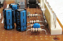
In all of my designs, I use a technique I first saw in MCI gear, where they place a carbon resistor in series with each power input. The power rating and value of the resistor is specifically chosen to cause the resistor to burn out if there is a short on a power rail on the board. Carbon resistors are preferable, since they usually tend to burn out at a lower temperature than a metal film type. They also stink when they burn out, alerting the user! These resistors should be spaced off the board to minimise damage if they do burn out. An additional benefit of having these series resistors is that when followed by a capacitor, they act as a filter for the power rail.
Alternatively, small solder-in fuses are sometimes used. Another common alternative is special fusible resistors. For us humble folks, sourcing these parts is usually difficult and it's a real nuisance in field servicing.
| Enlarge |
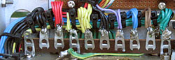
In a normal computer box, the Mains Earth is bolted to the power supply case. The remainder of the box is grounded via physical contact with the power supply case.
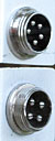
In this system, the wooden cabinet effectively insulates the Computer Power Supply from the Main Chassis. The Mains Earth from The Dog Box connects to the Chassis Ground via the Audio Power Connector. If anything, this arrangement is better than relying on the metalwork connections in a conventional box. Other metal items mounted in the cabinet such as the Blu-ray/DVD drive are also connected to the Chassis Ground Terminal.
For safety reasons, an additional earth wire runs from the Computer Power Supply case to the Chassis Ground Terminal. This ensures that if the Computer Power Supply is powered separately, the Main Chassis is still grounded. Another earth wire runs from The Dog Box to the Chassis Ground Terminal.
The common (0V) rail for the ±15 Volt Audio Power Supply is isolated from the Mains Earth in The Dog Box. Pins 1, 4 and 10 of the Power Distribution Tagstrip, The Chassis Ground Terminal and the ±15 Volt Audio Power Supply 0V are all directly connected to the chassis and this is used as Analogue Ground for the entire system.
In standard computer power supplies, the common (0V) rail is isolated from the Mains Earth inside the power supply. Instead, the 0V (black wires) from the Computer Power Supply is connected to the ground plane of the motherboard, which is in turn bonded to the Main Chassis via the metal mounting posts. This arrangement prevents ground loops. This means that the audio grounds coming from the sound chip on the motherboard should be very close to Analogue Ground (barring any design limitations of the motherboard).
An additional wire connects directly to the Computer Power Supply 0V and is used as Digital Ground for the system. Due to the heavy currents in the 0V wires between the Computer Power Supply and the motherboard, there will be a slight difference in potential between Digital Ground and Analogue Ground. These two grounds are wired separately to the peripheral boards and are isolated from each other. Any difference between these two grounds is taken into account by the electronics.
This arrangement gives the cleanest possible grounding for both the computer and the audio system.